Cutting Out the Complexity of Class 2 Posterior Composites
Front Matter and Copyright
Acknowledgement of Country1
We are learning on Noongar land.
The University of Western Australia
Copyright Notice2
Material used in this recording may have been reproduced and communicated to you by or on behalf of The University of Western Australia in accordance with section 113P of the Copyright Act 1968.
Unless stated otherwise, all teaching and learning materials provided to you by the University are protected under the Copyright Act and is for your personal use only. This material must not be shared or distributed without the permission of the University and the copyright owner/s.
Presentation Details3
- Presenter: Dr. Amit Gurbuxani
- Qualifications: MRACDS(DPH), BDS, MDPPH, FPFA, FICD, FADI
Introduction and Causes of Failure4
Why do most Class II composites fail?
Factors Influencing Clinical Success5
Factors that can influence the clinical success of Class II composite restorations:
- Patient characteristics
- Tooth preparation
- Matrix utilization
- Composite composition—dentin bonding
Today I’m going to show you how almost all of these failures come from only four critical steps.
Preparation Guidelines
Preparation Stages6
Direct Posterior Composite Stages7
| Feature | Description |
|---|---|
| Preparation Stage 1 | Outline form |
| Preparation Stage 2 | Rounded Internal Line Angle |
| Preparation Stage 3 | Flat floor |
| Preparation Stage 4 | Divergent Walls (Taper) |
| Preparation Stage 5 | Knife-edge Margins |
| Preparation Stage 6 | Exposed Dentin Surface |
Size and Location of Restoration89
The position of the tooth in the arch and the size of the cavity have been shown to be a factor in the success of a restoration. One study found the risk of failure in the molar area to be twice as high as for premolars, while another study placed the failure rate in lower molars as three times that of the upper premolars. Multi-surfaced restorations are also more prone to failure than single surface restorations. A study calculated that for every surface added to the restoration, a 40% increase in the failure rate resulted.
Opdam NJ, Bronkhorst EM, Roeters JM, Loomans BA. Longevity and reasons for failure of sandwich and total-etch posterior composite resin restorations. J Adhes Dent. 2007;9(5):469-475.
Lecturer — Restoration Selection
The decision between a composite and an indirect restoration depends on the amount of remaining tooth structure, the occlusion, and the type of loading.
- The clinician should question a filling material when more than two-thirds of the tooth is lost, although composite is not necessarily impossible.
- A large composite may function initially as a foundation, but an indirect covering restoration may be needed later.
Tooth Preparation Principles101112
Prepare only enough to:
- Remove disease
- Preserve enamel
- Allow matrix placement
Lecturer — Preparation Access
Preparation should provide enough access not only for caries removal and matrix placement, but also for restorative placement, finishing, polishing, and cleaning the margins.
- The preparation should not be extended solely to create convenience form.
- Opening the contact may be necessary when enamel is unsupported, the margin cannot be finished or cleaned, or matrix placement and composite finishing would otherwise be impossible.
Class II - Direct Posterior Composites
| ASTERIX | ASTERISK |
|---|---|
| 1 | 2 |
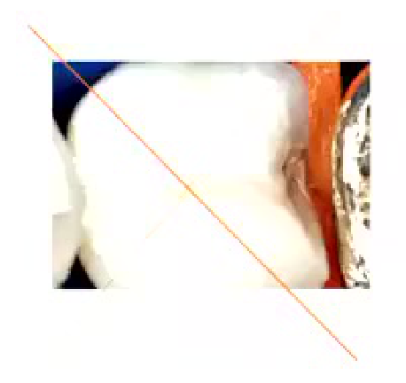
This is not Convenience Form?
AC
Lecturer — Starting Preparation
The preparation should begin centrally rather than immediately at the proximal margin, using a round or straight bur as appropriate. Starting centrally helps reduce the risk of damaging the adjacent tooth, after which the preparation can be extended for access.
- During learning, a Tofflemire band can protect the adjacent tooth when a needle bur is used, but the band must be checked because the bur can cut through both the band and the tooth.
- Smooth bur movement was recommended because repeated woodpecker-type movements may fracture thin enamel and create an irregular proximal area that is harder to seal.
 |  |
Pulpal Floor Depth1314
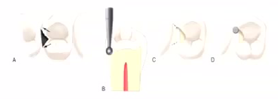
The pulpal floor is prepared with the instrument to a depth that is approximately 0.2 mm inside the DEJ. The instrument is moved to include caries and all defects facially or lingually or both, as it transverse the central groove. Every effort should be made, however, to keep the faciolingual width of the preparation as narrow as possible. The initial depth is maintained during the mesiodistal movement, but follows the rise and fall of the underlying DEJ.
Lecturer — Preparation Control
The pulpal floor should be prepared with awareness of the remaining tooth structure and the risk of damaging the adjacent tooth. The cavity should not be made deeper or wider simply for convenience, although it must still permit adequate material placement and matrix adaptation.
 |  |  |
 |  |
Beveling Decisions151617
 |  |  |
 | 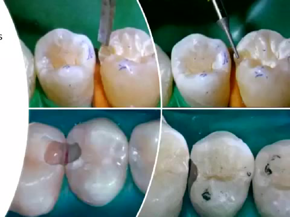 |
Margin Beveling Criteria18
Should I bevel this margin?
- Enamel? → Yes
- Small occlusal? → Usually no
- Visible proximal enamel? → Maybe
- Root dentine? → No
Should I bevel this margin?
- Enamel? → Yes
- Small occlusal? → Usually no
- Visible proximal enamel? → Maybe
- Root dentine? → No
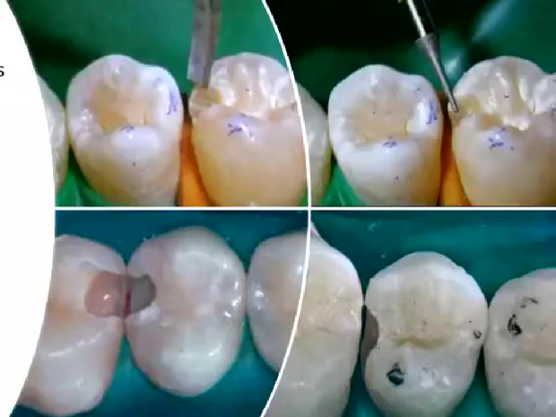
Occlusal Bevel Considerations19
Placement of occlusal bevels has demonstrated no benefit to the longevity of class 2 resin composite restorations.
Lecturer — Occlusal Bevels
Occlusal beveling was not recommended because it may leave a thin layer of composite in a stress-bearing area. Composite less than approximately 2 mm thick was described as more vulnerable to occlusal loading, chipping, and staining, even when the bevel initially looks acceptable.
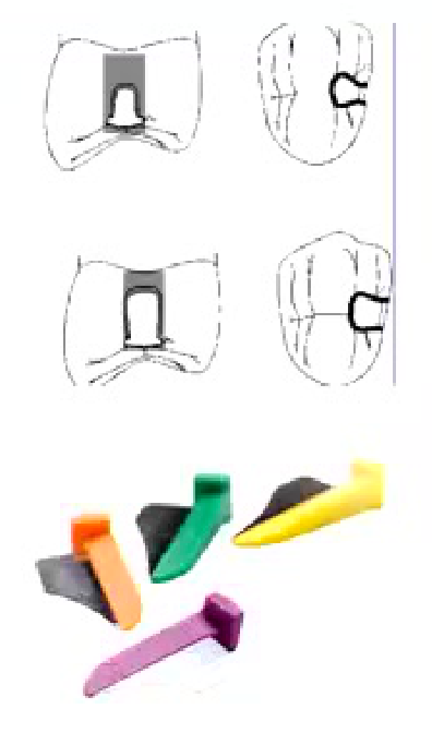
Pre-Wedging Technique
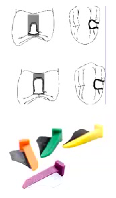
Benefits of Pre-Wedging202122232425262728
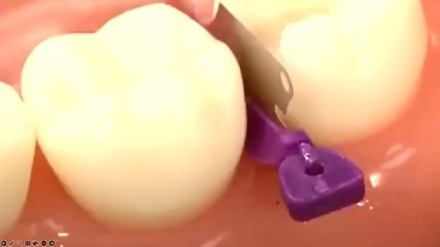
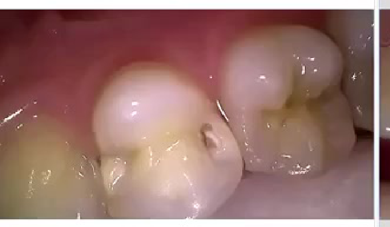
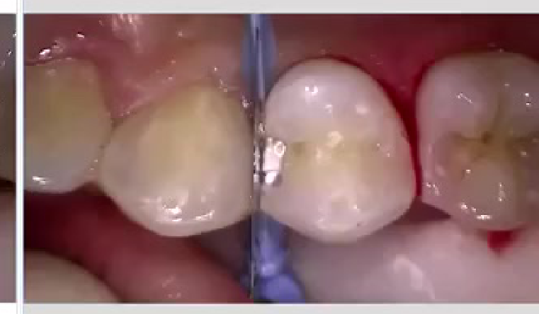
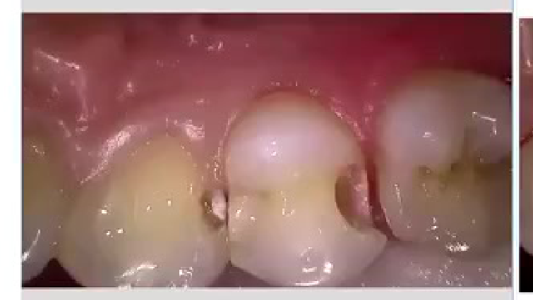
- Helps separate the teeth: easier to place matrix band – especially if preparing a slot technique or else if the caries is not extending beyond the contact.
- Some form of tooth separation, due to the PDL, such that after the restoration and the wedge is removed the tooth will return to its original position and lead to a tighter inter-proximal contact.
- Prevent damage to the adjacent tooth of restoration (e.g., using a fender wedge, wedge guard, etc.).
Lecturer — Pre-Wedging Details
The lecturer added several practical indications and limitations for pre-wedging.
- Perform pre-wedging before or during anaesthetic administration where appropriate.
- It provides access for caries removal and can open the contact sufficiently for preparation and finishing.
- A shaped wooden wedge may absorb moisture and extend further into the area.
- Pre-wedging is particularly useful for small proximal cavities and cavities located more buccally or lingually.
- Pre-wedging may complicate treatment when multiple restorations are being performed; for example, a distal-occlusal restoration may make access to a neighbouring mesial-occlusal restoration more difficult.
- A suggested quadrant-dentistry sequence is to complete one proximal restoration, complete the canine or another planned restoration, and then return to the neighbouring proximal restoration.
- Placement of occlusal bevels has demonstrated no benefit to the longevity of class 2 resin composite restorations.
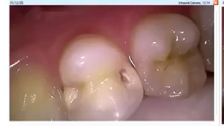
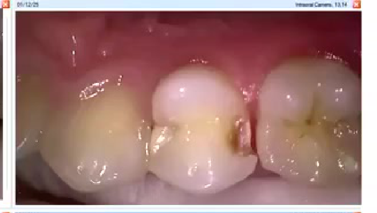
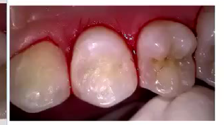
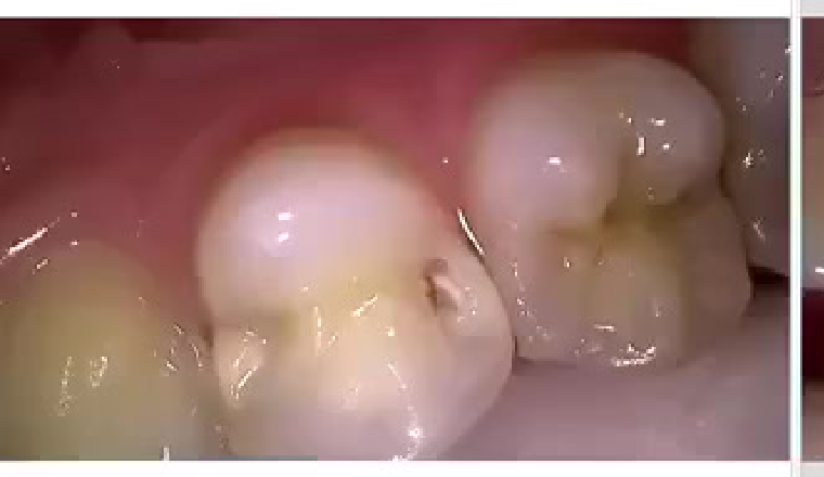
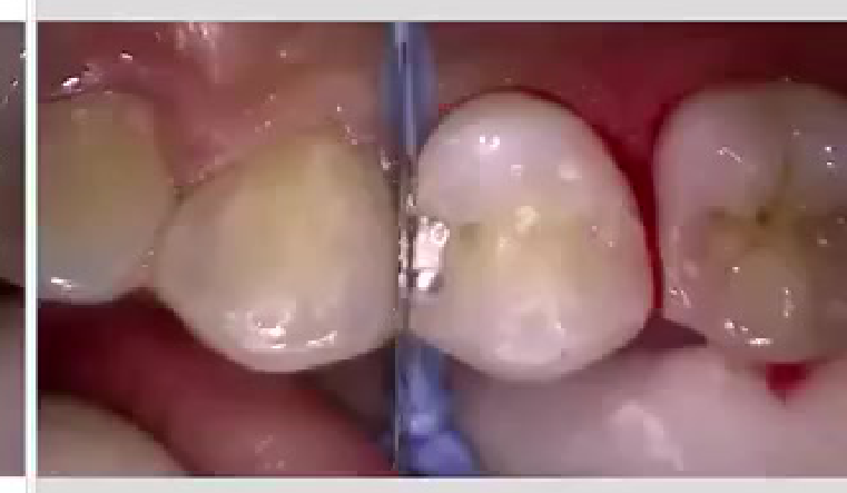
Matrix Systems and Techniques29
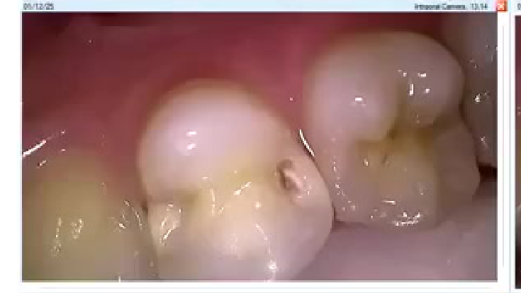
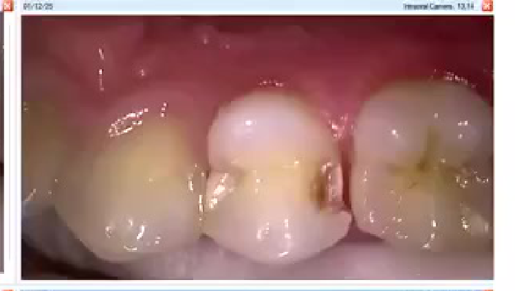
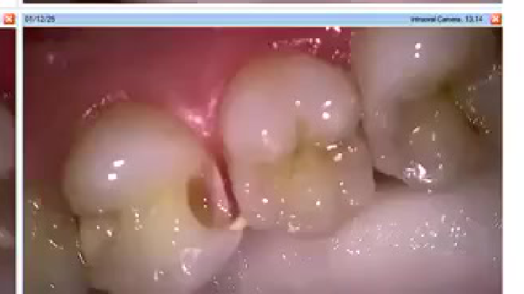
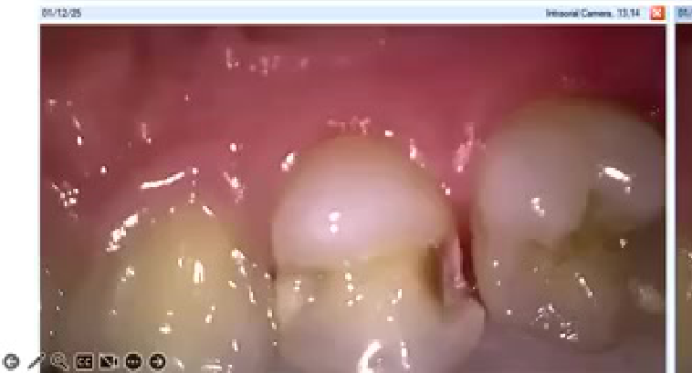
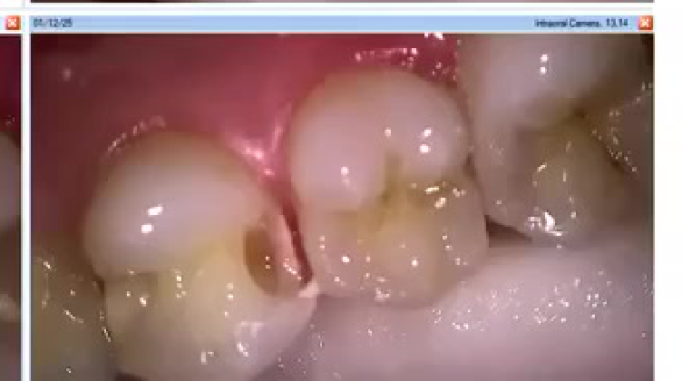
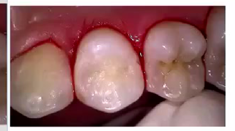
- INTRAORAL CAMERA, 14.14
- INTRAORAL CAMERA, 13
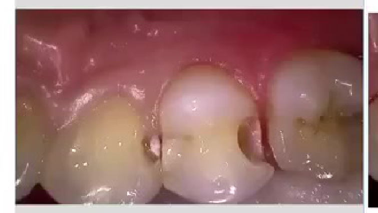 |  |
The Matrix Checklist30
Every matrix must achieve:
-
Gingival seal
-
Tight contact
-
Correct contour
-
Proper marginal ridge height
-
Correct matrix height and width
-
Proper adaptation to the tooth
-
Stability during wedge and ring placement
-
Clearance for finishing and polishing
-
Prevention of movement in mesial, distal, buccal, and lingual directions
Lecturer — Matrix Height
The matrix should be checked after placement and again after wedge placement.
- Gingival tissue may push the band coronally, particularly in a subgingival area.
- The top of the matrix should be approximately level with the adjacent marginal ridge.
- If the matrix is too high, the contact may be created too coronally and removed during finishing; if it is too low, the restoration may not achieve the correct contour.
- Matrix height can be assessed with a periodontal probe after cavity preparation, and bands are available in approximately 3.5, 4.5, 5.5, and 6.5 mm heights.
The matrix creates the contact; the composite does not. Most open contacts begin before composite placement if the matrix moves.
Tofflemire Versus Sectional Matrix Systems31
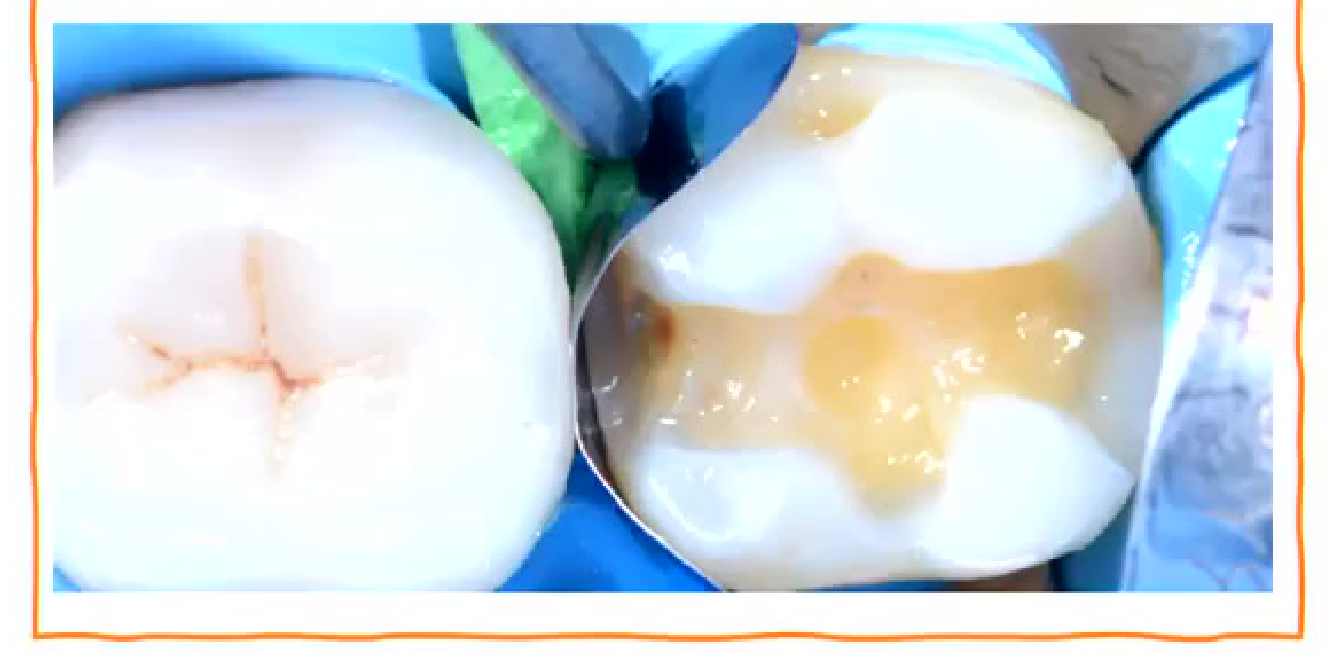
Tofflemire-Style System32
- Fails to restore proximal anatomy
- Thin contact at the marginal ridge
- Large food trap below
- Increased likelihood of fracture, occlusal interference, recurrent caries, and periodontal disease
Lecturer — Tofflemire Indications
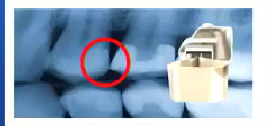
Tofflemire-style matrices can still be useful when basic contour is needed, when restoring larger areas, or when building up a tooth before creating a smaller mesial-occlusal or distal-occlusal preparation.
- The relatively straight band makes natural proximal contour difficult to reproduce, and the contact is often positioned in the upper third.
- An Automatrix may be used because it does not have the same large external band components as a conventional Tofflemire system.
Large Restoration Sequence
For a large restoration, the lecturer described building the tooth up with a Tofflemire-style matrix to establish the overall contour, then removing the matrix and cutting a smaller mesial-occlusal or distal-occlusal preparation into the composite.
- Re-etch, re-prime, and re-bond as required.
- Place a sectional matrix to establish the final proximal contact.
- This converts a complex restoration into a simpler Class 2 or Class 1-type situation.
 | 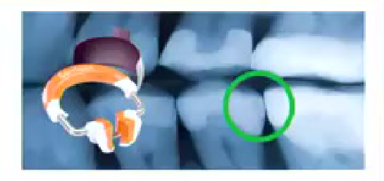 |
Composi-Tight® Sectional Matrix System
- Operator-friendly retaining system
- Naturally contoured bands
- Anatomically correct contacts
- Contacts at the height of contour
- Rings produce optimal tooth separation for excellent, tight contacts
- Rings may provide approximately 60–80 microns of separation
- Green rings are used for molars and yellow rings for premolars
- Nickel-titanium components return to their original shape after expansion
- Shorter and taller ring options are available
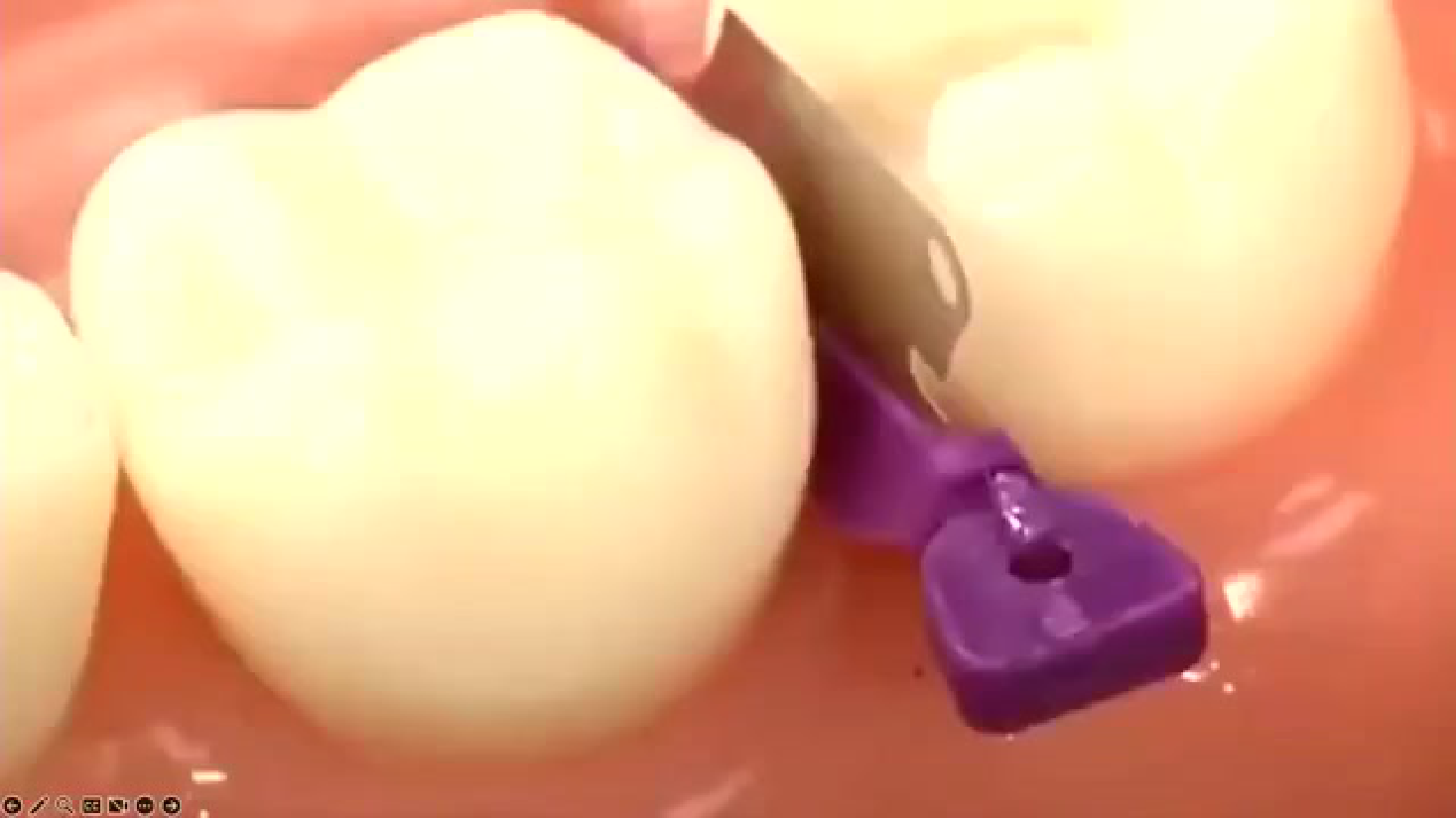
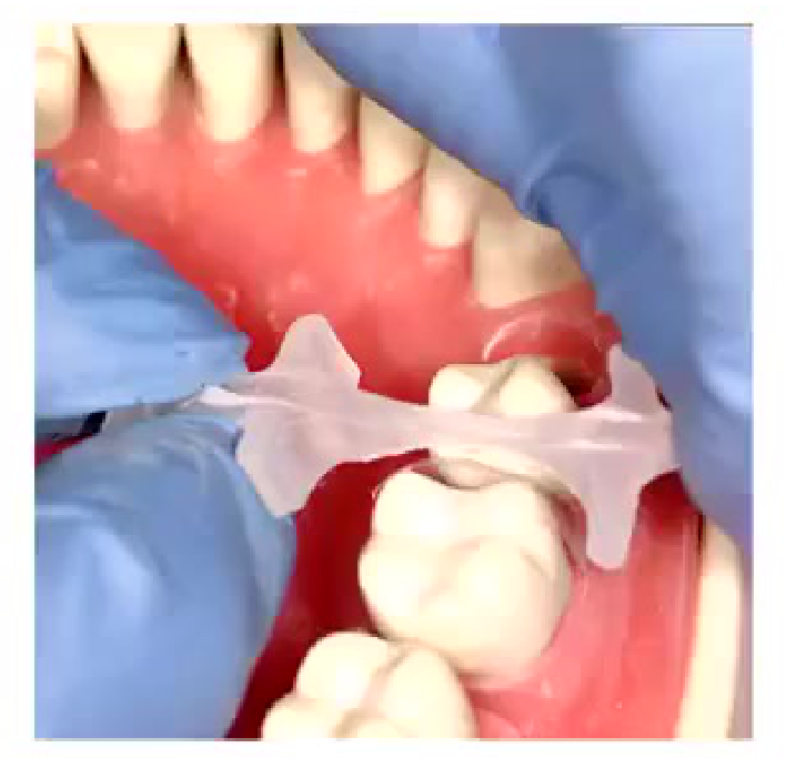
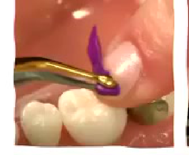
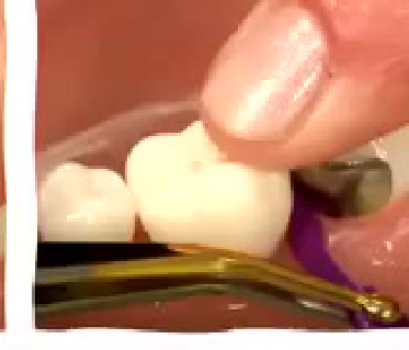
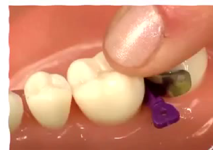
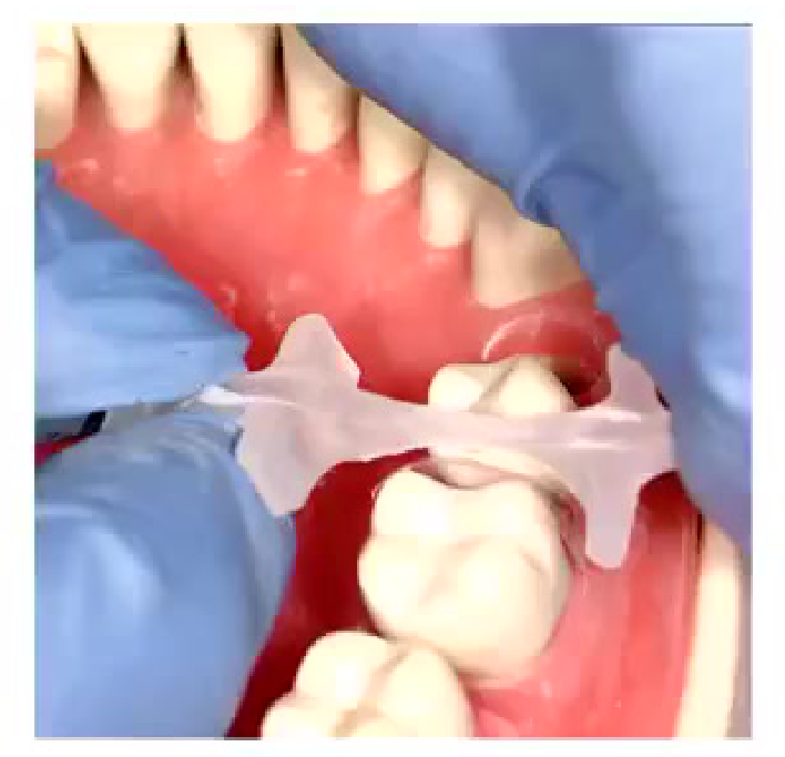
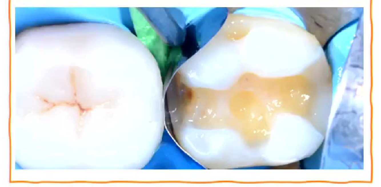
Wedge Placement Tips33343536
This particular wedge is called interproximator.
-
Remember to hold the band down from the coronal aspect while placing the wedge. Can use your finger to hold it in place.
-
You can use that finger which is holding the band down to rotate the wedge to place it from buccal or lingual.
-
Have a snug fit (no gap between proximal wall and the matrix). If gap is still present decide if large size wedge or double wedge or Teflon and wedge.
Lecturer — Wedge Stability
The wedge should be placed before the separation ring, and the band should be checked afterward to ensure it has not been displaced coronally.
- Use a mirror to inspect the gingival area.
- A larger wedge may improve adaptation, especially in a deep subgingival area; if it cannot be placed, the original wedge may be retained.
- A persistent gap can be managed with a larger wedge, double wedging, or Teflon, including a small roll tucked into the gap with a flat plastic instrument.
- A small amount of moisture or spray may help prevent Teflon from sticking to the instrument.
Double Wedging System37
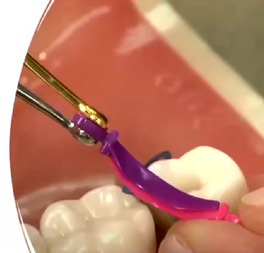
- Metal Sectional matrices: Variety of pre-curved, subgingival, and coated or non-coated
Lecturer — Protective Wedges
A Fender wedge combines a wedge with a small protective metal band and may protect the adjacent tooth during preparation.
- The metal component can subsequently be removed, leaving the wedge.
- A wedge guard may also be used to protect the adjacent tooth.
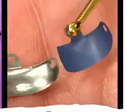
Component Features38
 |  |
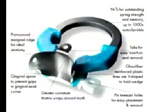 |
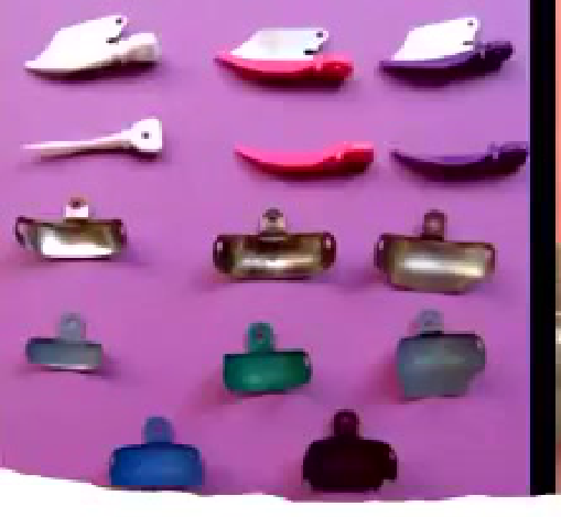
Sectional Matrices39
-
Ni-Ti for outstanding spring strength and memory, up to 1000x auto-retrievable
-
Pronounced marginal ridge for ideal esthetic anatomy
-
Tails for easy insertion and removal
-
Glass-fiber reinforced plastic bases are V-shaped to lock wedge
-
Gingival apron to prevent gaps in gingival-vertical corner
-
Greater curvature: Matrix wraps around tooth
-
Pin tweezer holes for easy placement and removal
-
Sectional matrices are also available as Teflon-coated, other shaped or pre-contoured, and clear matrix bands
-
Correct placement and adaptation are more important than the matrix material itself
-
The ring should be expanded sufficiently before placement to avoid moving the matrix or dislodging the wedge
-
Shorter rings may be useful when crown height is insufficient for a taller ring
Multiple Adjacent Restorations
When restoring two adjacent proximal surfaces, the lecturer recommended initially considering treatment in sequence rather than attempting both restorations at once.
- Restore one proximal surface, restore the neighbouring tooth, and then return to the remaining proximal surface.
- For a large distal-occlusal restoration beside a smaller mesial-occlusal restoration, use a Tofflemire-style matrix for the larger restoration and a sectional matrix for the smaller one.
- Correct the contour and contact after removing the matrices.
Audio Appendix
Additional Audio Content
The following sections from the lecture audio did not correspond to any heading in the main document.
Curing and Polymerisation
Curing Time and Technique
The required curing time depends on:
- The curing light.
- The intensity of the light.
- The material.
- The increment thickness.
- Whether the material is flowable, bulk fill, or a conventional composite.
A manufacturer’s instruction such as 20 seconds generally applies to a specified increment, often approximately 2 mm thick. If a thicker increment is placed, additional curing is required.
The lecturer’s main rule was that composite cannot be over-cured but can be under-cured. When uncertain, cure for longer.
Curing should include:
- Curing through the matrix where appropriate.
- Additional curing after the matrix is opened or removed.
- Curing from different directions.
- Repeated curing by the dental assistant where possible.
Curing light tips should be moved with small lateral movements rather than held in exactly one position. A light held 4 mm off-centre may lose approximately 85% of its irradiance in the area being cured.
The operator should:
- Keep the light close to the restoration.
- Position it accurately.
- Move it slightly to cover different areas.
- Check the wavelength and compatibility of the light with the composite.
- Have the curing light tested regularly.
A powerful light does not compensate for poor curing technique or uneven polymerisation.
Bonding and Isolation Details
Flowable Composite and Incremental Placement
Subgingival Bonding Considerations
Composite was described as being poorly tolerated by gingival tissue, whereas zirconia was described as being better tolerated. Therefore:
- Composite must be very well adapted in subgingival areas.
- Poor adaptation increases the likelihood of later failure.
- Bleeding and sulcular fluid must be controlled.
- The tissue must be managed before bonding.
- A temporary material may be preferable if a dry, clean field cannot be obtained.
Flowable Composite as a Liner
Flowable composite may be used as a thin liner to improve adaptation, particularly in:
- Deep proximal boxes.
- Irregular internal line angles.
- Areas where a conventional composite may not adapt smoothly.
- Cavities with developmental grooves or unusual proximal anatomy.
Flowable composite may also act as a flexible, stress-absorbing layer.
The recommended approach was:
- Place a thin layer, generally less than 1 mm.
- Adapt it to the internal line angles and proximal area.
- Avoid carrying it up into the occlusal, stress-bearing area.
- Cure it before placing the restorative composite.
Flowable composite has lower strength than the main restorative composite. If it is extended into a stress-bearing cusp area, it may chip or break down.
Rubber Dam and Clamps
Wingless clamps were recommended for composite procedures because they interfere less with matrix placement than winged clamps.
A floss tie should be attached to the clamp so that it can be retrieved if it dislodges.
Latex-free rubber dam was recommended because:
- Latex allergy may not always be identified.
- A rubber dam may remain in place for an extended period.
- Latex exposure may create a significant reaction.
Curing Modes
Some lights use staged or ramp curing. The purpose discussed included reducing the effects of heat and managing the initial polymerisation process.
The lecturer also noted that a constant hotspot may pull the composite toward the light. Staged curing and small movements may help reduce this effect.
Removing Flash
After the matrix is removed, the gingival area should be examined for flash.
Flash may be removed with:
- A sharp scaler.
- Other appropriate finishing instruments.
- A blade where permitted.
Excessive force with a scaler may chip the composite. Leaving flash can contribute to:
- Plaque retention.
- Leakage.
- Staining.
- Breakdown of the restoration.
Modelling Resin and Instrument Management
Modelling resin may be used to help shape composite and improve anatomy.
The lecturer distinguished this from dipping an instrument in bonding resin:
- Bonding resin may dilute the composite.
- It may contribute to staining.
- It may weaken the composite if incorporated into it.
- It may be used by some clinicians when modelling resin is unavailable, but this was not presented as equivalent.
Methylated spirits on gauze may be used to wipe instruments and make them less sticky. It evaporates quickly.
Microbrushes may help smooth composite or be used with modelling resin, but:
- They may not be strong enough for compaction.
- Poor-quality microbrushes may release fibres.
- Fibres incorporated into composite can create impurities and potential failure sites.
- The purple SDI Ultra Fine microbrush was mentioned as producing fewer fibres.
Conversion of Complex Restorations to Class 1 Form
A complex composite restoration can be made easier by first converting it into a Class 1-type shape.
The sequence described was:
- Establish the matrix and proximal wall.
- Place the flowable liner.
- Build the proximal wall.
- Adapt the composite carefully against the matrix.
- Create the general occlusal form.
- Add grooves and anatomy before finishing.
- Complete the remaining occlusal surface as a simpler Class 1 restoration.
This allows the matrix to establish the proximal height and contour, leaving the clinician to develop the occlusal anatomy.
Finishing, Polishing, and Anatomy
Light and Heat
Curing lights can become hot. The lecturer recommended placing the light against a thumb to appreciate the heat generated.
The lecture stated that the curing light does not provide sufficient time or intensity to cause irreversible pulpal changes, although it can feel hot on the lip or finger.
Developing Anatomy
Anatomy should be created during composite placement rather than being carved entirely during finishing.
- Establish the grooves while the composite is being placed.
- Do not rely on a bur to create all the anatomy later.
- A simple cross or “plus” pattern may be used as an initial guide.
- Grooves should be sufficiently defined before finishing.
- Finishing should refine the anatomy rather than remove it.
A common problem is flattening the grooves during finishing and polishing. The lecturer encouraged placing the grooves deliberately and not being afraid to create them clearly before curing.
Selective Etching
The lecturer described using selective enamel etching.
Etching time should be considered in relation to patient age and enamel thickness:
- Younger teeth may have thicker enamel and may require longer etching.
- Older teeth may have little remaining enamel and may require less etching.
- Etching a 75-year-old tooth in the same way as a young tooth may result in over-etching.
After etching, the clinician should avoid adding water in a way that causes the etched structure to collapse. Primer may help reopen and penetrate the surface, but water should not be used to re-wet the area unnecessarily.
Floss Technique
For certain situations, floss can be used to help secure and position the rubber dam.
- The floss can be twisted and pulled.
- It can be tied around the rubber dam frame.
- This helps pull the rubber dam downward.
- The technique may be especially useful for multiple Class 5 restorations.
- For individual situations, cheek guards or retraction cord may be sufficient.
Factors Influencing Clinical Success
The lecture identified several reasons why Class 2 composite restorations fail:
- High occlusal stress and increased occlusal loading.
- Recurrent caries and secondary caries.
- Leakage at the dentine-bonding or cemental-bonding interface.
- Fracture of the composite.
- Open contacts and marginal gaps.
- Moisture contamination.
- Poor anatomy.
- Inadequate curing.
- Poor isolation, including contamination from saliva, sulcular fluid, or gingival bleeding.
Four key clinical priorities were emphasised:
- Isolation.
- Matrix placement.
- Bonding.
- Curing.
Rubber dam isolation was strongly recommended. Although it can initially be difficult and time-consuming, becoming efficient with rubber dam placement makes restorative procedures easier and also develops skills useful for bonding other restorations.
Patient Characteristics
Patient age and tooth condition influence the expected success of a composite restoration.
- In a younger patient, there is usually more enamel available for bonding.
- In an older patient, enamel may be worn away, leaving more dentine and sclerotic dentine.
- Bonding to dentine is more compromised than bonding to enamel.
- Older patients may also have:
- More involuntary movement.
- Greater time-related concerns about returning for treatment.
- Existing restorations such as mesial-occlusal or distal-occlusal restorations.
- Root-surface or subgingival caries.
- Dry mouth or other conditions that complicate isolation.
The clinician should consider how long the restoration needs to last and should manage expectations, particularly where a large composite is being used as a foundation for a possible future indirect restoration.
Bonding to Dentine and Cementum
Bonding to dentine and cementum is weaker because these tissues contain:
- More organic structures.
- More tubules.
- More fluid.
The bond involving MDP in these areas may break down more quickly. Therefore, a subgingival margin involving cementum or dentine is more compromised than an enamel margin.
The lecturer also discussed older open- and closed-sandwich techniques using glass ionomer cement:
- An open-sandwich technique involved placing glass ionomer cement and leaving it exposed to the environment, with composite placed over the remaining area.
- A closed-sandwich technique involved covering the glass ionomer cement with composite.
- These approaches were described as problematic because glass ionomer cement may wash out.
- A defect may then develop, even if secondary caries does not occur.
- The different elastic moduli of glass ionomer cement, composite, and remaining tooth structure may contribute to failure.
Avoiding Voids
The composite must be adapted carefully to the matrix and the flowable layer.
- A flat plastic instrument may be used to push composite against the matrix.
- The composite should be pressed against the wall and then adapted repeatedly.
- This reduces the chance of voids.
- The matrix should be properly adapted before composite placement.
The lecturer noted that the flowable layer may adapt well while voids remain in the conventional composite above it. Therefore, the restorative composite must also be carefully adapted.
Deep Subgingival Margins and Gingival Management
Clinical Cases
Case: 17 MO Subgingival Caries Scenario
Question
Scenario: A student presents a clinical scenario of a 17 MO deep subgingival caries with severe gingival bleeding, adjacent to a 16 with a DO filling, where standard matrix bands cannot adapt subgingivally.
What’s shown: A verbal description of the clinical situation (deep subgingival margin, bleeding, adjacent tooth with filling).
Consider: How to manage isolation, bonding, and matrix placement in this difficult subgingival scenario.
Answer
Observations:
- Subgingival margin with severe bleeding.
- Bonding to dentin/cementum is weaker and more prone to breakdown.
- Standard matrix bands cannot adapt properly subgingivally.
Reasoning: The lecturer walks through options: if bleeding is uncontrolled, a temporary GIC may be placed. Otherwise, use retraction cord with a hemostatic agent followed by a medium/thick rubber dam to push the papilla away. Then, trim a V-ring matrix band to avoid interference from the adjacent 16 filling, and use double wedging or Teflon to adapt the band subgingivally.
Takeaway: In deep subgingival situations with bleeding, control the tissue with cord and rubber dam, and adapt the matrix carefully using wedges or Teflon to ensure a seal without relying on weak subgingival bonds.
Case: MO146 Cusp Capping Decision Picture
Question
Scenario: The lecturer refers to a picture of a tooth with an MO preparation where decay has spread underneath, and asks when to decide to cap a cusp.
What’s shown: An image of a posterior tooth with an MO cavity and occlusal markings (blue articulating paper) showing where the bite hits.
Consider: At what point during preparation should the dentist decide to cap a cusp, considering the occlusion and remaining tooth structure.
Answer
Observations:
- Decay has spread underneath the occlusal surface, undermining enamel.
- Occlusal load (blue marks) falls on the compromised area.
Reasoning: If the occlusal load falls on an area where enamel is undermined and the margin will be half-composite/half-tooth, the cusp must be capped. Checking occlusion before preparation helps map where the load is, preventing unexpected failures when the patient bites down later.
Takeaway: Always check and map occlusion before starting cavity preparation to identify if a compromised cusp will bear functional load and require cusp coverage.
Case: Lower Crown Preparation Picture
Question
Scenario: The lecturer shows a picture of a lower crown where a dentist attempted to drill out a small area of caries.
What’s shown: An image of a lower crown with damaged gold and a wedge, showing a small, difficult-to-access carious lesion.
Consider: Whether this preparation represents “convenience form” or minimal preparation, and how to approach such lesions.
Answer
Observations:
- The preparation is small and difficult to access.
- Adjacent structures (gold crown, wedge) were damaged during the attempt.
Reasoning: The lecturer explains that this is not true “convenience form.” Minimal preparation should follow the principles of decay removal while ensuring enough access to pack the material and place/clean the matrix, rather than creating a tiny, unmanageable hole that damages adjacent structures.
Takeaway: Minimal preparation does not mean creating an unmanageable access; ensure sufficient access for proper matrix placement and material adaptation without damaging adjacent teeth.
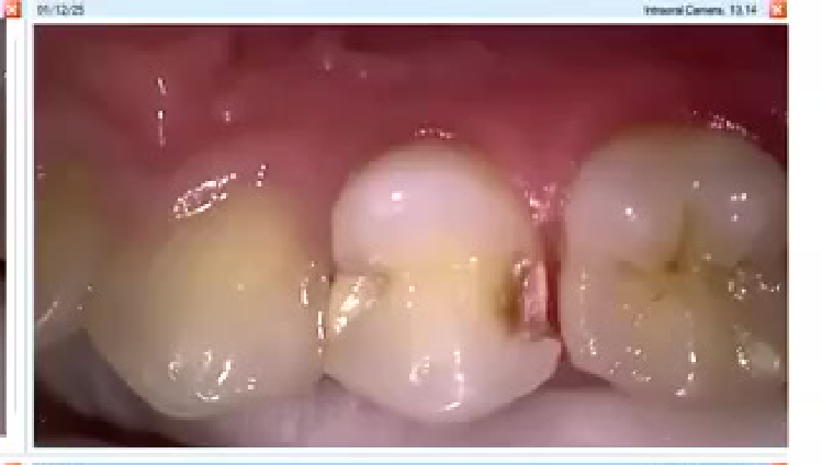
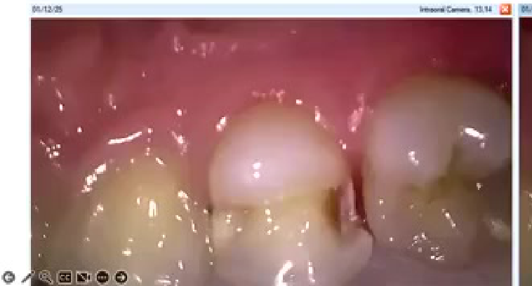
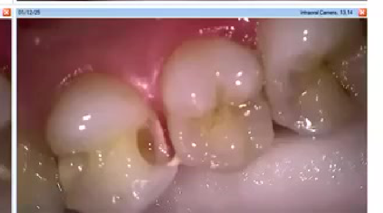
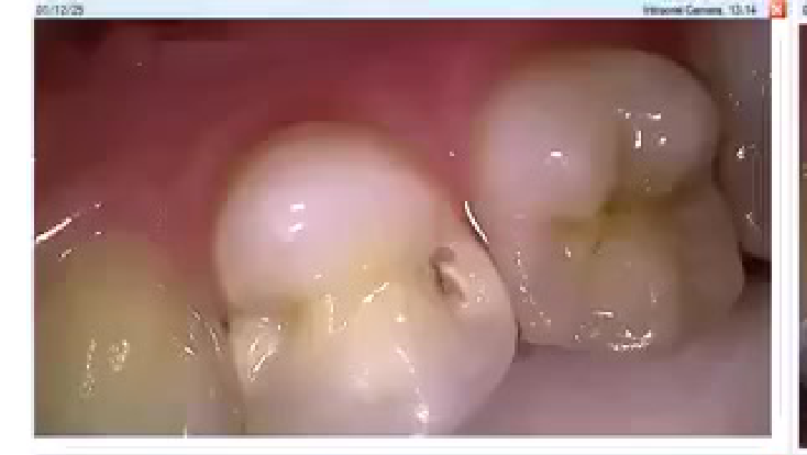
Case: December Cavity Preparation Case
Question
Scenario: The lecturer presents a clinical case from December showing cavity preparation on a posterior tooth without a rubber dam.
What’s shown: Images/video of the cavity preparation, showing moisture control issues (wet cotton roll), pre-wedging with a wooden wedge, and the use of a straight bur and spoon excavator.
Consider: How to manage moisture and clean the cavity effectively without a rubber dam, and whether to bevel the margins.
Answer
Observations:
- Moisture is present (wet cotton roll) due to lack of rubber dam.
- Pre-wedging was done before preparation using a wooden wedge.
- A straight bur and sharp spoon excavator were used for cleanup.
Reasoning: Pre-wedging extends the PDL space, making it easier to place the matrix and clean the proximal box. Without a rubber dam, moisture control is much harder, highlighting the benefit of rubber dam. Beveling is discussed: bevel enamel margins in non-stress bearing areas, but avoid occlusal bevels to maintain the required 2mm composite thickness for strength.
Takeaway: Pre-wedging facilitates matrix placement and proximal cleanup, but rubber dam is highly recommended for moisture control; bevel only non-stress bearing enamel margins.
Case: Flowable Composite Adaptation and Voids Picture
Question
Scenario: The lecturer shows a picture illustrating the adaptation of flowable composite versus regular composite in a proximal box, highlighting the presence of voids.
What’s shown: An image showing a flowable composite liner adapting well to the gingival margin, but with visible voids in the adaptation layer, alongside regular composite.
Consider: What the image reveals about the adaptation of flowable composites and the subsequent steps required to avoid failure.
Answer
Observations:
- The flowable composite adapts well to the irregular gingival margin.
- There are visible voids present in the adaptation layer.
Reasoning: While flowable composites excel at adapting to deep, irregular proximal boxes, the image shows that voids can still form. The lecturer emphasizes that after placing the flowable liner, the dentist must take time to properly adapt the subsequent regular composite layers to eliminate these voids and clean up any flash to prevent leakage and secondary caries.
Takeaway: Flowable composites improve adaptation in deep boxes, but voids can still occur; careful adaptation of the overlying composite and thorough flash removal are critical to prevent restoration failure.
Footnotes
-
Original PDF page 1: [[L2 Class II composites [good][extended]_slides.pdf#page=1|L2 Class II composites [good][extended] slides, p.1]] ↩
-
Original PDF page 2: [[L2 Class II composites [good][extended]_slides.pdf#page=2|L2 Class II composites [good][extended] slides, p.2]] ↩
-
Original PDF page 3: [[L2 Class II composites [good][extended]_slides.pdf#page=3|L2 Class II composites [good][extended] slides, p.3]] ↩
-
Original PDF page 4: [[L2 Class II composites [good][extended]_slides.pdf#page=4|L2 Class II composites [good][extended] slides, p.4]] ↩
-
Original PDF page 5: [[L2 Class II composites [good][extended]_slides.pdf#page=5|L2 Class II composites [good][extended] slides, p.5]] ↩
-
Original PDF page 10: [[L2 Class II composites [good][extended]_slides.pdf#page=10|L2 Class II composites [good][extended] slides, p.10]] ↩
-
Original PDF page 6: [[L2 Class II composites [good][extended]_slides.pdf#page=6|L2 Class II composites [good][extended] slides, p.6]] ↩
-
Original PDF page 7: [[L2 Class II composites [good][extended]_slides.pdf#page=7|L2 Class II composites [good][extended] slides, p.7]] ↩
-
Original PDF page 9: [[L2 Class II composites [good][extended]_slides.pdf#page=9|L2 Class II composites [good][extended] slides, p.9]] ↩
-
Original PDF page 8: [[L2 Class II composites [good][extended]_slides.pdf#page=8|L2 Class II composites [good][extended] slides, p.8]] ↩
-
Original PDF page 11: [[L2 Class II composites [good][extended]_slides.pdf#page=11|L2 Class II composites [good][extended] slides, p.11]] ↩
-
Original PDF page 12: [[L2 Class II composites [good][extended]_slides.pdf#page=12|L2 Class II composites [good][extended] slides, p.12]] ↩
-
Original PDF page 13: [[L2 Class II composites [good][extended]_slides.pdf#page=13|L2 Class II composites [good][extended] slides, p.13]] ↩
-
Original PDF page 14: [[L2 Class II composites [good][extended]_slides.pdf#page=14|L2 Class II composites [good][extended] slides, p.14]] ↩
-
Original PDF page 16: [[L2 Class II composites [good][extended]_slides.pdf#page=16|L2 Class II composites [good][extended] slides, p.16]] ↩
-
Original PDF page 17: [[L2 Class II composites [good][extended]_slides.pdf#page=17|L2 Class II composites [good][extended] slides, p.17]] ↩
-
Original PDF page 20: [[L2 Class II composites [good][extended]_slides.pdf#page=20|L2 Class II composites [good][extended] slides, p.20]] ↩
-
Original PDF page 15: [[L2 Class II composites [good][extended]_slides.pdf#page=15|L2 Class II composites [good][extended] slides, p.15]] ↩
-
Original PDF page 18: [[L2 Class II composites [good][extended]_slides.pdf#page=18|L2 Class II composites [good][extended] slides, p.18]] ↩
-
Original PDF page 19: [[L2 Class II composites [good][extended]_slides.pdf#page=19|L2 Class II composites [good][extended] slides, p.19]] ↩
-
Original PDF page 21: [[L2 Class II composites [good][extended]_slides.pdf#page=21|L2 Class II composites [good][extended] slides, p.21]] ↩
-
Original PDF page 22: [[L2 Class II composites [good][extended]_slides.pdf#page=22|L2 Class II composites [good][extended] slides, p.22]] ↩
-
Original PDF page 23: [[L2 Class II composites [good][extended]_slides.pdf#page=23|L2 Class II composites [good][extended] slides, p.23]] ↩
-
Original PDF page 24: [[L2 Class II composites [good][extended]_slides.pdf#page=24|L2 Class II composites [good][extended] slides, p.24]] ↩
-
Original PDF page 25: [[L2 Class II composites [good][extended]_slides.pdf#page=25|L2 Class II composites [good][extended] slides, p.25]] ↩
-
Original PDF page 26: [[L2 Class II composites [good][extended]_slides.pdf#page=26|L2 Class II composites [good][extended] slides, p.26]] ↩
-
Original PDF page 27: [[L2 Class II composites [good][extended]_slides.pdf#page=27|L2 Class II composites [good][extended] slides, p.27]] ↩
-
Original PDF page 28: [[L2 Class II composites [good][extended]_slides.pdf#page=28|L2 Class II composites [good][extended] slides, p.28]] ↩
-
Original PDF page 29: [[L2 Class II composites [good][extended]_slides.pdf#page=29|L2 Class II composites [good][extended] slides, p.29]] ↩
-
Original PDF page 30: [[L2 Class II composites [good][extended]_slides.pdf#page=30|L2 Class II composites [good][extended] slides, p.30]] ↩
-
Original PDF page 32: [[L2 Class II composites [good][extended]_slides.pdf#page=32|L2 Class II composites [good][extended] slides, p.32]] ↩
-
Original PDF page 31: [[L2 Class II composites [good][extended]_slides.pdf#page=31|L2 Class II composites [good][extended] slides, p.31]] ↩
-
Original PDF page 33: [[L2 Class II composites [good][extended]_slides.pdf#page=33|L2 Class II composites [good][extended] slides, p.33]] ↩
-
Original PDF page 34: [[L2 Class II composites [good][extended]_slides.pdf#page=34|L2 Class II composites [good][extended] slides, p.34]] ↩
-
Original PDF page 35: [[L2 Class II composites [good][extended]_slides.pdf#page=35|L2 Class II composites [good][extended] slides, p.35]] ↩
-
Original PDF page 36: [[L2 Class II composites [good][extended]_slides.pdf#page=36|L2 Class II composites [good][extended] slides, p.36]] ↩
-
Original PDF page 37: [[L2 Class II composites [good][extended]_slides.pdf#page=37|L2 Class II composites [good][extended] slides, p.37]] ↩
-
Original PDF page 38: [[L2 Class II composites [good][extended]_slides.pdf#page=38|L2 Class II composites [good][extended] slides, p.38]] ↩
-
Original PDF page 39: [[L2 Class II composites [good][extended]_slides.pdf#page=39|L2 Class II composites [good][extended] slides, p.39]] ↩